1A: Onshape Fundamentals - Section 1
Exercise 3: More Extrudes
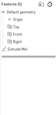
In this exercise, you'll extrude four rectangles by two inches symmetrically — and turn them into tubes.
Use just one extrude feature. What happens?
Don't forget: use the Tube Converter after extruding.
Click the boxes below to expand them! (Check out the website feature guide)
Looks a bit weird? Click here after trying it.
If you followed the instructions and used a single extrude, all four rectangles probably merged into one big block. In real life, you don't want parts fused together like this unless you meant to.
Can you figure out how to extrude them individually to keep them separate?
If you need to restart, here's a quick video showing how to delete your bad tubes:
Click Here if you fixed your extrude.
Manually doing four extrudes is tedious. There's a better way!
-
Delete your old extrudes.
-
Use the
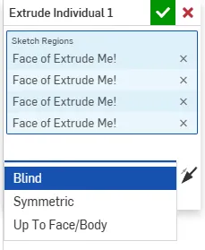
Extrude IndividualFeaturescript you added in required course tools. - (Hit
Alt+Cand search "extrude individual" if needed.)
This tool lets you extrude multiple sketch regions separately, all in one step.
Also, if you click the "Symmetric" option inside Extrude Individual, you can force symmetry.
Exercise 3.1: Sketching Basics
In the last exercise, you extruded an existing sketch. Now it's your turn to create the sketch yourself.
When we sketch, we use rectangles to represent box tubes in 2D, and use dimensions and constraints to lock everything into place.
Follow along with the video below to practice sketching fundamentals in Onshape.
Key Sketching Points
- Dimensions control distances (like making a rectangle exactly 5 inches wide).
- Constraints define relationships (like locking a rectangle edge to another).
- Yellow dotted lines show automatic constraints — use them!
- The Origin is your anchor. Attach sketches to the origin whenever possible.
- Blue is bad — a blue sketch means it's not fully defined yet. Everything should turn black.
- Less is better — use the fewest dimensions necessary to fully lock down your design.
What You Learned
- How to extrude multiple tubes separately
- How to create and constrain a sketch
- How to make rectangles properly
- How to use basic dimensions and relationships
- How to mirror using construction lines
Exercise 3.2: Adding Rails
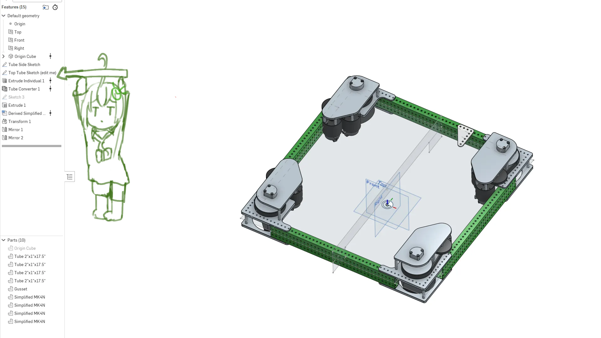
Now let's apply this to the robot.
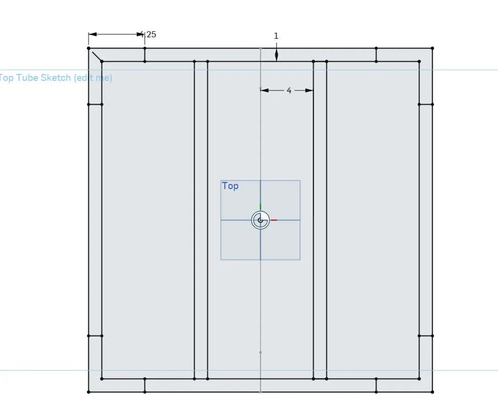
Open the Top Tube Sketch in the Exercise 3.2 part studio and add two cross tubes that are 8 inches apart.
Tip
Double-click the sketch in the feature tree to edit it.
Draw the new rails yourself. Only use one new dimension total.
The only numbers you should see:
- 4.25" (gap between modules)
- 1" (tube width)
- 8" (distance between cross rails)
Check Your Work
Click here after you finish your sketch
Here's an optimized way to sketch it:
Compare your approach to the video.
What did you do differently?
How would you avoid mistakes like that next time?
After you're done checking your work and reviewing your approach, move on to the next exercise.